
 Windows
 Mac
MacUpload STEP files of your components
Add a 3D model to your part, define the connector’s cavity designations and configure its contacts and accessories.

01 / SCHEMATIC
Connect devices, define pin functions and trace the electrical design. Power, grounds, twisted pairs and named circuits stay visible in one schematic.

02 / 2D HARNESS
Turn the circuit into a dimensioned harness layout. Arrange connectors and terminals, shape the branches and label the destinations.

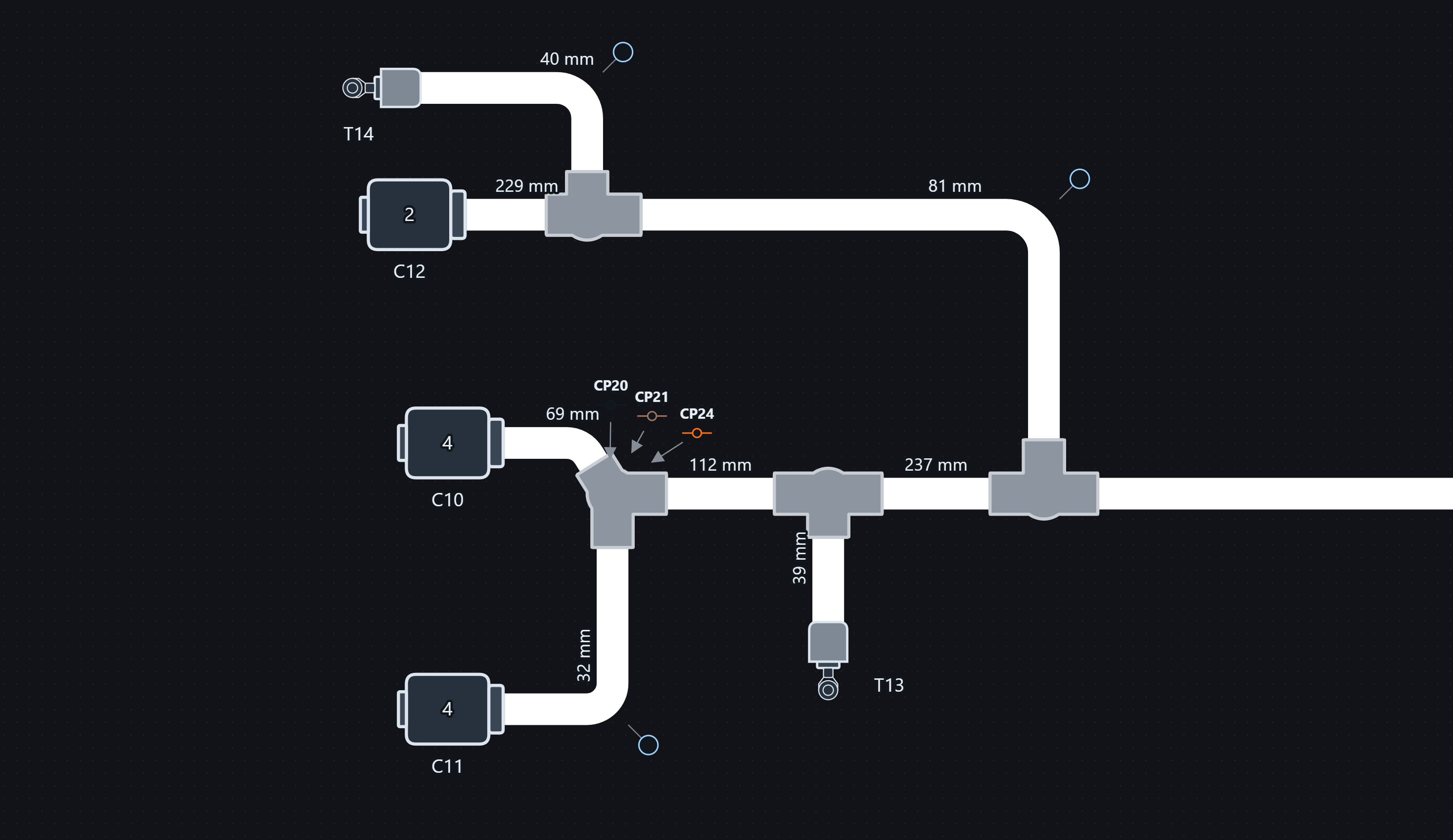
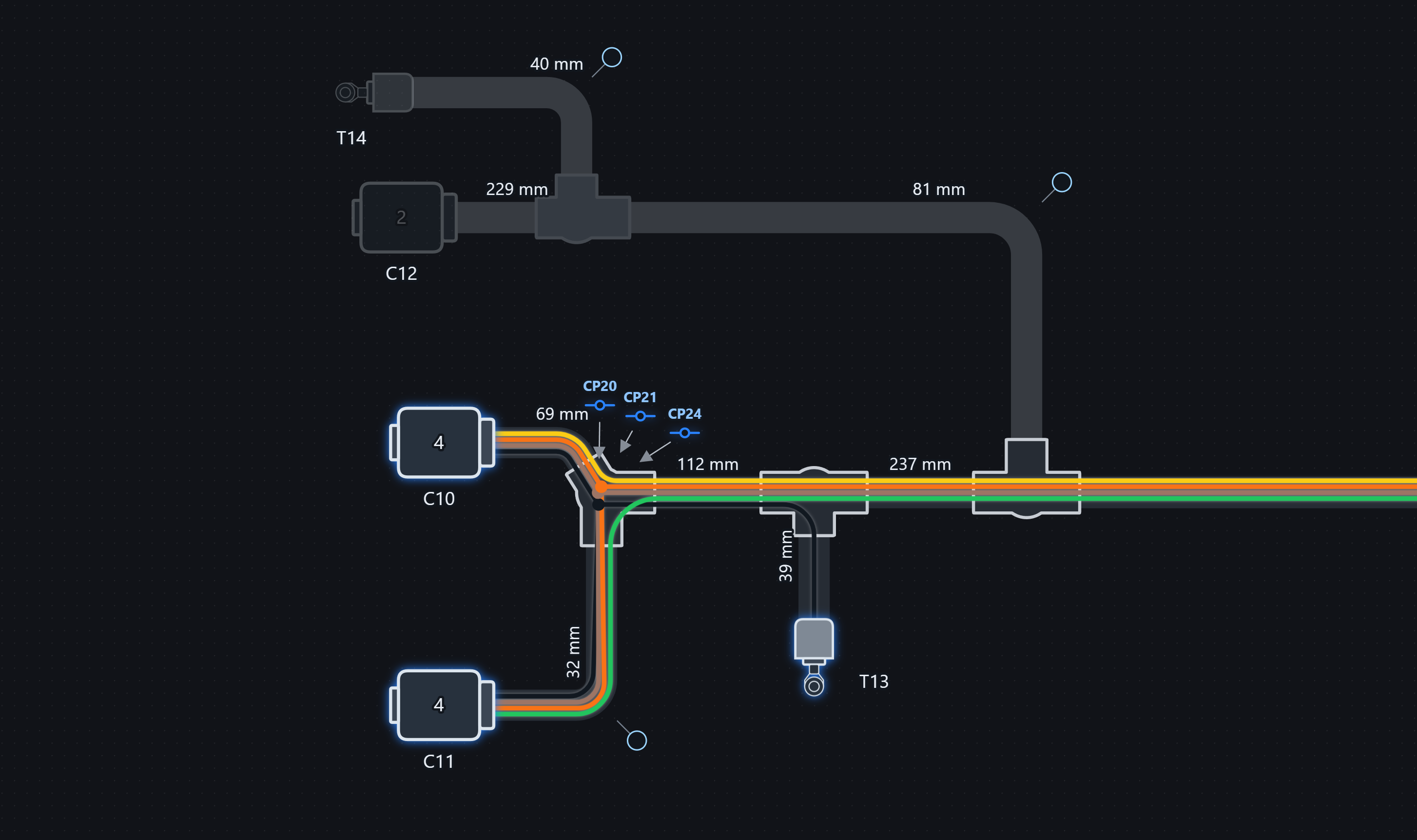
03 / INSIDE THE BUNDLE
04 / 3D HARNESS
Place components in 3D space and route the wiring harness between them. Import reference CAD models to achieve an accurate design the first time.
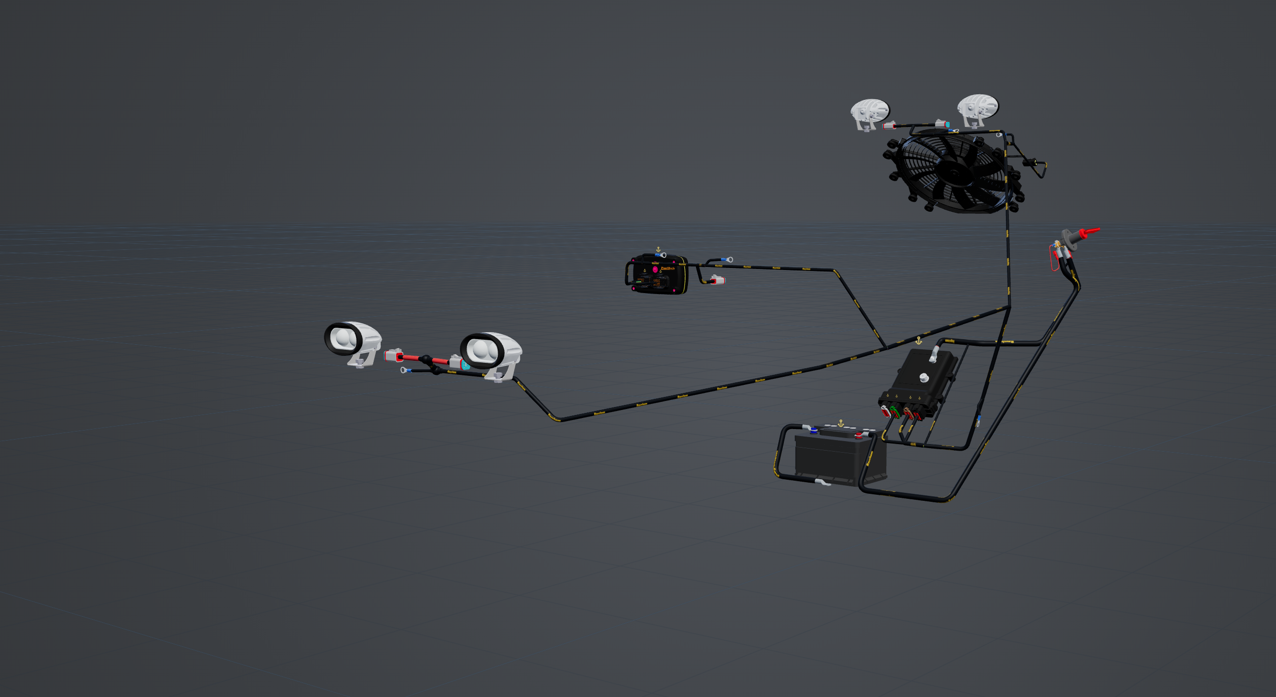
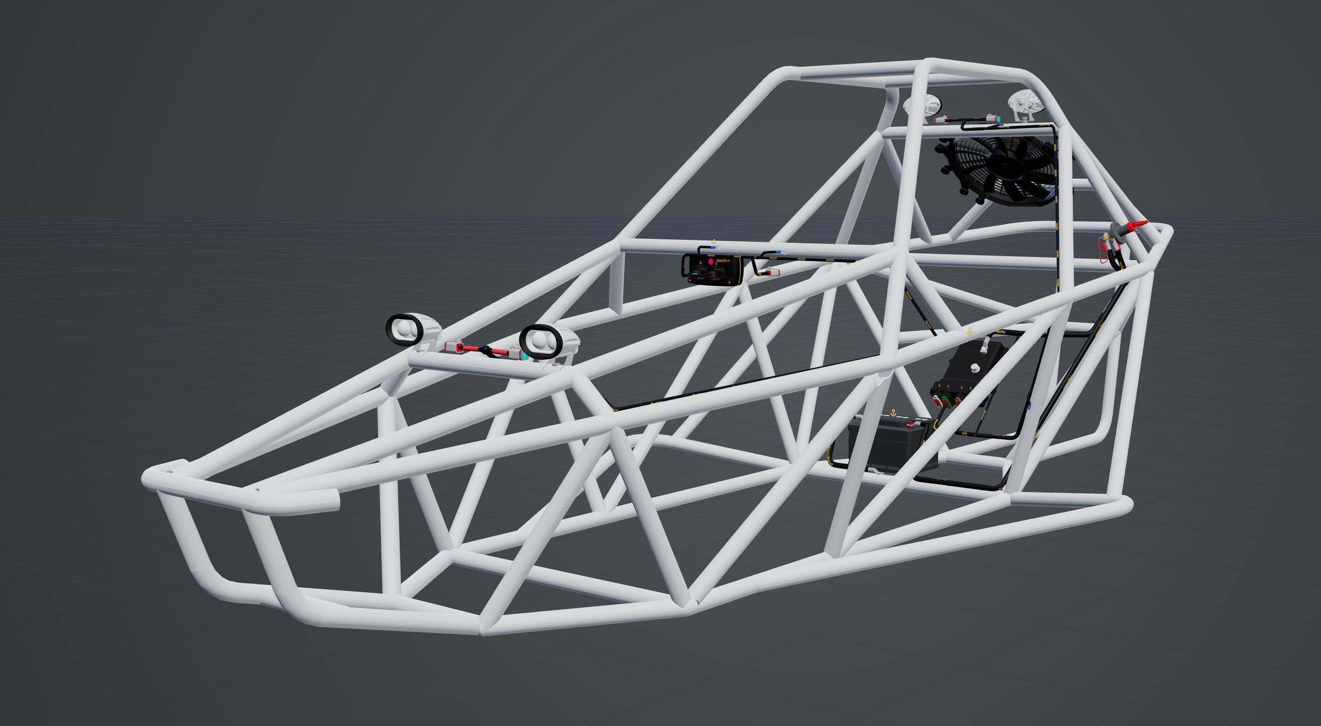
Coverings, wires and junctions are modelled in 3D space, ensuring issues are found at the design stage instead of the production stage.
05 / SPLIT PANES
View each pane side by side for easy cross-referencing.
06 / CONNECTIONS
Review conductor IDs, wire colours and gauges alongside their endpoints, circuit names and lengths.
From a connector cavity to a junction, the connections list brings the electrical and physical details into one searchable view.

07 / PARTS LIBRARY
Choose from an expanding list of parts in the global library, or remain completely offline with your own local library.

Add a 3D model to your part, define the connector’s cavity designations and configure its contacts and accessories.
Inspect the housing and its accessories together in 3D.

08 / PARTS
Bring connectors, terminals, wires and other project parts together with their manufacturers, quantities and costs.
See which parts are included, which are unused and which components still need a part assigned.

09 / DOCUMENTATION & EXPORT
Export embeddable HTML, PDFs, Excel spreadsheets and videos to share your design and build documentation.

10 / LIVE DIAGNOSTICS
Store the LoomView file on the PDM for easier maintenance and diagnostics later on. See live output states, voltage and current alongside your wiring design, and trace circuits through the schematic, 2D and 3D harness.
Loom3DHardwire Electronics Pro PDM Configurator
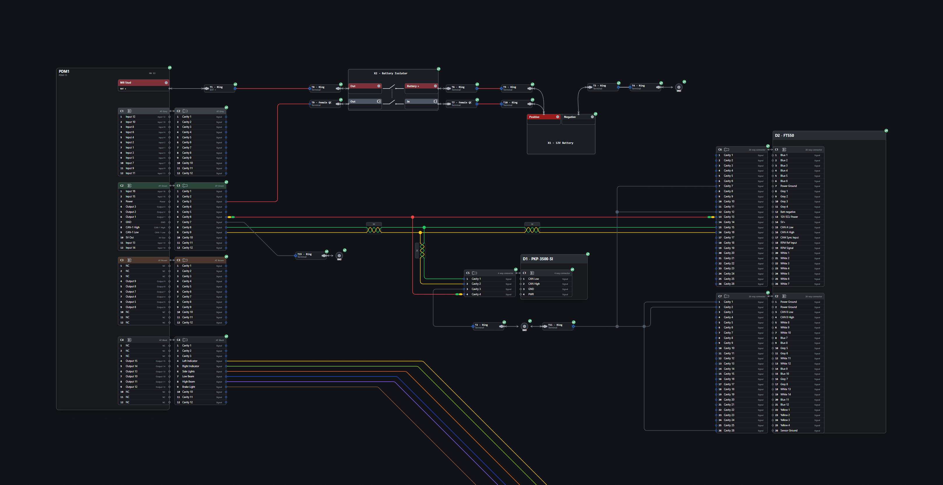
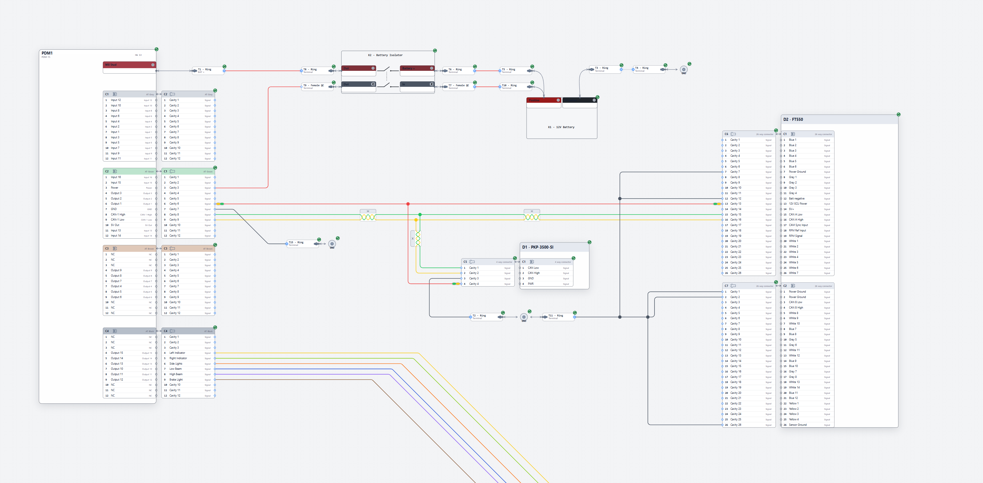
11 / LIGHT & DARK
 Dark mode
SEE IT IN ACTION
Follow a separate, simple worked example from a blank project to documentation. The current instruction appears above the video as it plays.
01 / Create a blank project
On Home, choose New project.
The video could not be played. Open the MP4 directly.